Capabilities and features
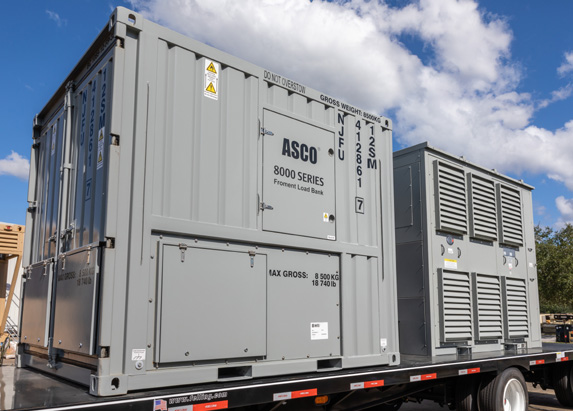
ISO Style containerized construction. Vertical discharge
Walk-in control room for easy access to control, switchgear and optional power circuit breakers
Air inlet covers provide protection from dirt and moisture during transport
Polycarbonate screens in control and switchgear enclosures protect all live parts from accidental contact
Four Lift Frame: Quantity Four (4) integral lifting holes plus Fork Pockets Built into Container Base
Load Control
Sigma 2 microprocessor based load bank control system module – Installed with Voltage and Current Transformers to provide control interface for all the functions within the Load Bank for individual or multi-unit control. Provides intelligent, fast, user friendly, accurate control and instrumentation with outstanding test features and data acquisition capabilities.
One or more Sigma load banks can be linked together and operated using either the:
1) Sigma IHT3 – Intelligent Handheld Terminal, or
2) Sigma PC Load Control Software from your own computer.
Other options available include control via MODBUS from a customer’s separate system or, Sigma Load share to automatically maintain a minimum load. (included)
Sigma IHT3 (v4) with instrumentation and a standard 10m lead – The Sigma ‘Intelligent Handheld Terminal’ IHT3, with full instrumentation is connected to the load bank with a standard 10m reinforced multi-core cable fitted with quick release plug and socket connectors.
Sigma extension lead (100m) supplied on reel
HMI touch screen module
Multi-functional display: located inside the control room area.
Local load selection and activation, Measured power, Selected power Diagnostic display down to component level.
Sigma PC load control software v2 with USB interface
The Sigma PC load control system software, in conjunction with an industrial standard PC (not included), replaces the standard IHT for control of the load bank. The Sigma PC load control system provides enhanced load control and full data acquisition capabilities.
Construction: The frame of the load bank is constructed from 2mm ‘Zintec’ steel, folded and welded to form a monocoque construction. Double skinned recessed doors allow easy access to the separate enclosures for control, switch gear and power connections. The double skinned, horizontal discharge duct with stainless steel heat shield contains the resistive load elements and the cooling fan. Stainless steel mesh screens on the main air inlet and outlet provide protection against access to hazardous parts to IP1X. All electrical enclosures are to IP54. High quality two-pack industrial acrylic paint system applied to an electro-plated zinc base and low-bake finish.
Load connections: Load Bank will have Cam-Lock type connectors for load connection on the outside of the Load Bank enclosure.
Load elements: Load banks use replaceable, non-finned sheathed elements. The outer sheath is made from stainless steel to give good corrosion resistance. The heating element is an 80/20 nickel-chrome wire embedded in compacted magnesium oxide powder, giving good thermal and insulation properties. The elements are very conservatively rated and there is no need for cooling fins to dissipate the heat into the airflow. This ensures that foreign matter or a loosely fitting fin cannot possibly cause hot spots and therefore ensures high reliability.
The elements are designed to operate continuously at up to 800°C (red/orange). The actual temperature is below 500°C (dull red). This gives a wide margin of safety and very long life. Load tolerance is within 2½ % of total capacity. Elements are continuously rated at the specific voltage. Short-term tests with fluctuations up to 10% above rated voltage are permissible. Tests at lower voltages, with a corresponding reduction in overall rating, may be carried out. Power is proportional to voltage squared.
Auxiliary power: The fan and control circuit may be powered from an external auxiliary supply or from the supply on test, provided it is of the correct voltage and frequency. Lower voltages and other frequencies must be tested using the external supply. On static load banks, connection is by internal terminals. On movable load banks, an IEC 60309-2 plug and socket with a three-position switch enables quick and easy connection. Dual 50/60Hz Fan & Control Circuit: 380/420V, 50Hz and 440/480V, 60Hz.
Safety features:
- An emergency stop/disconnect switch gives full isolation of the fan and control supply.
- A 110 Volt AC control circuit transformer provides isolation and operator safety.
- Stop/start buttons ensure the load bank will not automatically restart. On static load banks provision is also made for the connection of remote stop/start buttons.
- The fan motor is fully protected with fuses and a thermal overload. Movable load banks are also fitted with phase rotation detection to automatically ensure correct airflow direction. Single phasing protection is provided by the overload. Thermal detectors are fitted to protect against overheating in the resistive duct and switchgear enclosure.
- Over voltage protection for the control and load circuit is provided by Sigma load control if specified.
- Each element group and its associated contactor are protected by an HRC fuse. This is very important when testing large capacity power supplies, due to the possible high fault currents.
- The load contactors are interlocked with the fan controls to ensure load can be applied only when the fan is running.
- Internal access is restricted by key operated door catches. Polycarbonate screens behind the doors prevent accidental contact with live parts.
Transformer: 3400kVA, dry type, Aluminum wound, VPI, special with load break (medium voltage quick-connect), 4160:480V, 3- phase, 60Hz, 150C rise, 120” long, 96” deep, 102” high, 14,000 pounds.
Semi-trailer and interconnect: Trailer for transformer and load bank, drop deck, air ride, 40-foot overall length, semi-trailer. Semi-trailer is 102” wide, 41” high (loaded height to lower deck), 40’ long (29’ lower drop deck). Includes mounting for load bank and transformer, ABS, air suspension, two speed front landing gear, dual axle, standard semi-trailer air hook ups, electrical 7-way plug. Primed and finish painted black.
CHARACTERISTICS
Manufacturer: PD Power Systems, LLC
Part No.: PS-LB-3250/RR
Rated: 3125KVA at 0.8pf 480V, 3-phase, 50/60Hz Continuous Duty Rated
Compromising:
2500KW at 480V, 3-phase, 60Hz
1875KVAR at 480V, 3-phase, 60Hz
Fully variable power factor capability
Fan Motor & Control Circuit: Dual 50/60Hz 380-420V, 3-phase; 440-480, 3-phase, 60Hz
Dimensions (Load bank):
Height (ft.) – 8.5
Width (ft.) – 8
Length (ft.) – 10
Weight (lbs.) – 18,750
Trailer & Skid Base
Mounted Load Banks
Worldwide service and support
PD Power Systems provides support for military products around the world:
- Support at various existing and future locations of the U.S. military around the globe.
- Commissioning and maintenance support services globally
- Critical parts inventory at critical locations and around the world
- Support for engineering and technical data for all products and services
Program Management
Having fielded thousands of units throughout the globe, PD Power Systems has a successful record of power distribution and power generation equipment with the United States military.
For more information, please contact:
General Inquiries
Email: info@pdpowersystems.com
Sales
Email: sales@pdpowersystems.com
Main Phone: 1-866-460-7377
Online: Contact Inquiry Form
